Ceramic vs. Film: Choosing the Right Technology for Your Safety Capacitors
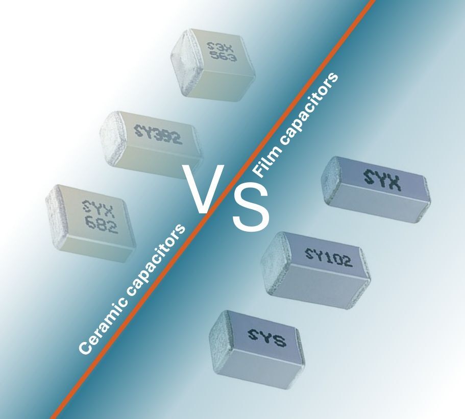
When selecting a safety capacitor for your application, you typically have two choices in dielectric material – ceramic and film. To select the right technology for your application, it is important to both understand your requirements and the differences between what each material has to offer.
General Considerations for Selecting a Safety Capacitor Technology
When comparing whether to use an MLCC or film capacitor for your safety capacitor, you need to consider the capacitor’s construction, performance characteristics, and suitability for specific safety roles as well as the capacitor’s:
- Temperature range
- Size constraints
- Voltage rating
- Capacitance value
- Cost
Let’s further explore the characteristics of both MLCCs and film capacitors.
Ceramic Capacitors
In general, for line-to-ground configurations, or Class Y capacitors, safety requirements dictate that failure must not result in a conductive path that could pose a shock hazard. MLCCs, when properly rated, can meet these requirements. Some benefits of using MLCCs include the following:
- Compact size, allowing for high capacitance in a small footprint, which is ideal for spaceconstrained designs
- Cost-effective manufacturing makes ceramics attractive for high-volume, cost-sensitive projects
- Low equivalent series resistance (ESR) and equivalent series inductance (ESL) support effective high-frequency EMI suppression
Some challenges with using ceramic include that ceramic generally has a lower voltage rating than film, which can limit its use in high-power designs. Additionally, while some MLCCs can withstand high temperatures and humidity, others may be susceptible to performance drift under environmental stress, which can impact long-term reliability.
As a result, ceramic is well suited for Y1 and Y2 safety capacitors, especially those used in appliances, chargers, or compact consumer electronics where space and cost are driving factors.
Film Capacitors
Film capacitors are most commonly used in Class X applications where they are installed across the AC line. Therefore, these capacitors must be able to withstand large voltage surges and recover from a dielectric breakdown with only a small reduction in capacitance.
Advantages of using a film capacitor include the following:
- High voltage tolerance that enables reliable performance
- Self-healing properties that allow the capacitor to recover from small dielectric failures without catastrophic failure
- Excellent stability over time and varying environmental conditions to ensure long service life and consistent safety compliance
Since film capacitors are typically larger in size, it may be challenging to use these capacitors in densely packed assemblies. Film capacitors also typically cost more than ceramic options, which may be a consideration for cost-sensitive markets. As a result, film is typically a good fit
for X1 and X2 safety capacitors used in industrial equipment, power supplies, or any design that must withstand line surges and operate over extended periods.
Selecting the Right Dielectric for Your Design
The choice between using ceramic or film for your safety capacitors requires a clear understanding of the capacitor’s role, requirements, and environmental operating conditions. Ceramic capacitors offer compactness and cost advantages, making them well suited for many Class Y roles. Film capacitors, with their robust voltage handling and reliability, are typically the preferred choice for demanding Class X applications.

Table 2. A side-by-side comparison of ceramic and film technologies for safety capacitors.
Safety Capacitors for EMI Filtering in the PFC Stage of an AC/DC Converter
One common use for safety capacitors in an AC/DC converter is the PFC circuit. PFC circuits are required to ensure the input current is in phase with and proportional to the input voltage, improving power quality and efficiency. But the high-frequency switching that occurs in the PFC circuit can generate significant EMI. To prevent this noise from disrupting nearby electronics or violating regulatory limits, EMI filters are essential. This next section provides a comprehensive set of steps for selecting the appropriate safety capacitors to perform EMI filtering in the PFC stage of an AC/DC converter.
Step 1: Determine Your Filtering Requirements
To determine your filtering requirements, you first need to understand exactly what kind of noise you’re dealing with. To do this, examine your conducted emission test data to identify frequency bands where noise exceeds regulatory limits such as those set by the International Special Committee on Radio Interference (CISPR) or the Federal Communication Commission’s (FCC) Code of Federal Regulations Part 15.
Let’s look at a real-world example. If your circuit fails by 25dB at 500kHz, you need to select a filter that provides at least 30dB attenuation at that frequency to ensure a 5 dB buffer for safety and component tolerance. This type of analysis provides a clear target for what your capacitor needs to block, forming the foundation for all subsequent choices.
Step 2: Match the Capacitor to Your Voltage Conditions
You also need to ensure your capacitor can safely withstand your circuit’s voltage levels, including both the nominal line voltage and any expected voltage surges. When doing this, keep in mind that AC and DC voltage ratings are not interchangeable. A capacitor rated for 275V DC may not be suitable for 275V AC applications; therefore, be sure to choose capacitors explicitly rated for AC voltage.
It is also important to consider the impact of transients. For example, in an industrial environment with frequent switching, your capacitor may experience repetitive surges. Choose a safety capacitor that exceeds your worst-case voltage scenario, not just your nominal input.
Step 3: Evaluate the Circuit’s Configuration
To determine the appropriate circuit configuration, you need to consider your device’s impedance characteristics, required filtering performance, and any space constraints. The common configurations you might consider may range from single grounded capacitors to more complex three-element circuits.
Step 4: Assess Key Performance Parameters of Potential Capacitors
With general specs defined, you should then dig into the electrical characteristics of candidate capacitors including:
- Capacitance Value: Will determine filtering effectiveness at specific frequencies, which should be the dominant noise frequencies in your emissions profile.
- ESR: Lower ESR generally means lower losses and better performance, especially under high-frequency switching.
- Dissipation Factor (DF): Represents the total losses in the capacitor and is related to both ESR and reactance.
- Q Factor: This is the ratio of stored versus lost energy per oscillation cycle, and, in some industries, is used as a measure of capacitor performance.
Balancing these characteristics is key to achieving effective filtering without excess heat or instability.
Step 5: Consider Construction and Installation Methods for the Capacitor
Capacitors come in many shapes and mounting styles. Therefore, it is important to evaluate the physical aspects of the capacitor including:
- Size and Form Factor: The capacitor must fit within your design constraints while still meeting electrical performance and thermal management requirements.
- Installation Method: Options can include solder-in, bolt-in, or screw-in mounting and will impact how well your capacitor can handle mechanical stress and heat dissipation
- Environmental Ratings: Temperature range, humidity resistance, and vibration ratings can all impact the performance and lifespan of your capacitor.
Step 6: Verify Safety Certifications and Failure Modes
Since PFC EMI filters connect directly to mains power, safety isn’t optional, it’s mandatory. Only use capacitors with clearly marked safety approvals, such as UL, VDE, or ENEC. Additionally, keep in mind that Class X capacitors, or “across-the-line” capacitors, should fail short to trigger upstream protection (like a fuse or breaker) and Class Y capacitors, or line-to-ground capacitors, must fail open to avoid shock hazards.
Step 7: Test and Validate Under Real-World Conditions
Finally, even the best-specified capacitor is only as good as its performance in your real system. Once installed, retest your product for both conducted and radiated EMI to verify compliance with relevant standards. And, keep in mind, EMI filtering often involves a bit of iteration and tuning, so be ready to make adjustments.
Explore Knowles’ Comprehensive Safety Capacitor Portfolio
Choosing the right safety capacitor isn’t just about ticking boxes on a datasheet, it’s about ensuring your circuit can effectively do its job and is safe for long-term operation. To support this, Knowles offers a broad range of safety-certified multilayer ceramic (MLC) and film capacitors designed to meet rigorous standards and support diverse applications from electric EV battery systems to industrial power supplies. Below is a breakdown of what we offer.
Class X Safety Capacitors
Our Class X offerings range from 5.6 pF to 40 μF and are available in both MLCC and film formats.
Key options include:
- SYX/UYX family: These are both X1 and Y2 capacitors and are ideal for use in high-voltage EV battery systems
- MXT Class X2: Film capacitors that meet demanding 85/85 temperature-humidity-bias (THB) standards, making them ideal for use in harsh environments.
Refer to Table 3 below for a full comparison of our Class X product lines.
Class Y Safety Capacitors
Our Class Y safety capacitors, which are most commonly MLCCs, range from 5.pF to 1 μF and include the following options:
- SYX/UYX family
- SYS: Class X1/Y2 safety capacitors that have a humidity robustness grade III rating and 5kV impulse and a 1kVdc rating approved by TÜV and UL
- MYH series: Film capacitors that are AEC-Q200 qualified and meet a 2,000-hour THB life test. Ideal for use in many applications including motors, automated meter readers, uninterruptible power supplies (UPS), power supplies, charging systems, and appliances
Table 3 provides a comparison of the characteristics of our Class Y safety capacitor offerings.

Table 3. A summary comparing many of our most popular Class X and Class Y capacitors.
A New Line of High-Performance Safety-Certified Capacitors
Knowles also recently released a new range of X1/Y2 safety-certified surface-mount MLCCs. With a voltage rating between 310Vrms and 500Vrms, including the first class Y2 MLCC on the market featuring a voltage rating as high as 500Vrms (Table 4), these new MLCCs are ideal for ensuring safe operation of the high-power AC/DC converters required for a variety of industrial and automotive applications.

Table 4. The electrical characteristics of the newest Knowles safety capacitors.
Key features of our new range of safety-certified MLCCs include the following:
- High Working Voltage: Voltage rating and maximum capacitance value of 12nF in 310Vac class Y2
- Critical Safety Features in a Compact Case: An innovative design that offers a creepage distance of up to 5 mm minimum packed into a 2720 case size, reducing required board space
- Higher DC-Rated Voltage: 1,500V in compliance with EN60384-14 Annex H
- Tested for Operation in Harsh Environments: Rated to humidity grade IIIB (85°C/85%RH,1000hr)
- Wide Operating Range: -55C to 125C
As with all our safety-certified MLCCs, these new capacitors are available AEC-Q200 qualified
and with a flexible termination option using FlexiCap™, our proprietary flexible epoxy polymer
termination material.
(c) Peter Matthews - Knowles precision devices

your
local specialist
for