Aluminum Electrolytic Capacitors vs. Film Capacitors
The progress in semiconductor design sets the trend in current and future devices of power electronics: it manifests itself particularly in smaller dimensions, as well as in higher voltages and switching frequencies. Referring to intermediate circuit capacitors, this trend leads to aiming at higher energy densities and larger current loads, and – at the same time – decreasing space.
Under these conditions, especially aluminum electrolytic capacitors and plastic film capacitors offer advantageous solutions. Jianghai has both technologies in the production program and this article gives an overview on the major differences between aluminum electrolytic capacitors and film capacitors.
DC-Link Capacitor Technology Comparison
Aluminum Electrolytic vs. Film Capacitors
By Dr. Arne Albertsen, Jianghai Europe Electronic Components GmbH
Applications of intermediate circuit capacitors
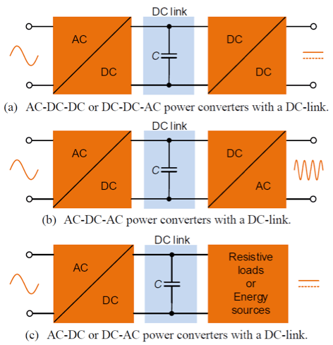
The intermediate circuits (DC-link) of converters frequently utilize capacitors. The main tasks of these capacitors are (a) smoothing of the ripple voltage superimposed on the DC-bus voltage and (b) the provision of electrical energy. Figure 1 shows the block diagrams of converters that have a DC link.
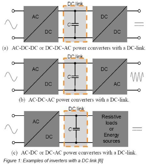
Application examples for inverter comprise wind turbines, photovoltaic power systems, UPS (uninterruptible power supplies), electric motors, electric vehicles, lighting and welding equipment. Depending on the application, different demands for lifetime, reliability, temperature, dielectric strength, current-carrying capability, and other parameters of the intermediate circuit capacitor may exist. Because there is no universal capacitor solution for all applications, a selection of suitable capacitors on the basis of the specific requirements of the respective application is necessary.
Comparison of electrolytic capacitors and film capacitors
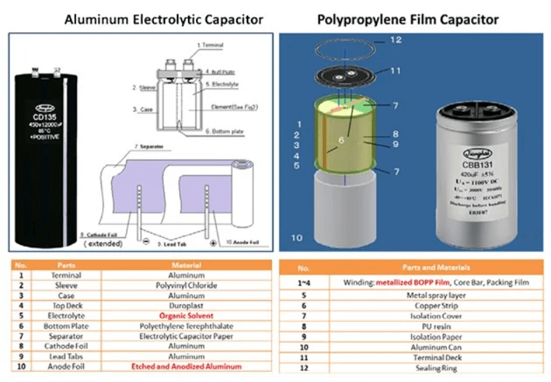
Figure 2 shows the construction and the essential materials of an aluminum electrolytic capacitor (left) and a polypropylene film capacitor (right).
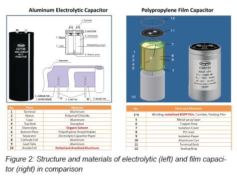
Structure and materials of electrolytic capacitor (left) and film capacitor (right) in comparison
While the active part of electrolytic capacitors, the so-called wound cell, consists of aluminum (anode and cathode foil), paper, and electrolyte, the film capacitor is made of metal-coated plastic film that builds its electrodes.
The peculiarity of the electrolytic capacitor is its “liquid cathode”: the total surface of the highly roughened aluminum anode foil, coated with aluminum oxide as dielectric, can be fully contacted through the electrically conductive electrolyte, to realize the high specific capacitance of this technology [1].
The film capacitor is made from dry materials: the capacitor plates consist of metal vapor, which was been deposited on a plastic film that serves as dielectric. Often, the dielectric is polypropylene, consisting of polymer chains that are preferably oriented in longitudinal and horizontal direction (also known as BOPP for biaxially oriented polypropylene).
The different electrical properties of the two technologies originate from the different materials used in them. Figure 3 shows the energy densities for some selected dielectrics in comparison. Actual aluminum electrolytic capacitors have up to ten times higher energy density than polypropylene film capacitors.
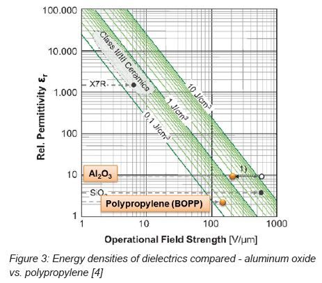
Energy densities of dielectrics compared - aluminum oxide vs. polypropylene
Because the electrical current flow in aluminum electrolytic capacitors is facilitated by ions flowing through the electrolyte, the viscosity of the electrolyte has a significant influence on the temperature dependence of the ESR values: at low temperatures the electrolyte becomes more viscous and inhibits the free movement of ions, leading to a higher ESR value. At temperatures above 60 °C, the ESR hardly changes [1]. Also the capacitance of aluminum electrolytic capacitors decreases with falling temperatures by a double-digit percentage. However, ESR and capacitance of the film capacitor show themselves largely unimpressed by temperature fluctuations: the capacitance over the entire temperature range varies only about 3 ~ 5 %, and ESR values remain nearly constant.
These parameters show a similar performance vs. frequency: for electrolytic capacitors, capacitance and ESR both exhibit a strong frequency dependency [1], while film capacitors show almost constant capacitance and ESR values across the technically interesting frequency range from 100 Hz ~ 200 kHz.
The film capacitor offers higher rated voltages than the e-cap: the voltage proof of a single element can be up to 1500 V, while e-cap rated voltages are limited to 650 V [3]. The voltage (and ripple current) limitations of individual electrolytic capacitors requires multiple capacitors to be connected in series and in parallel to build a “capacitor bank”. When connecting electrolytic capacitors in series, an active or passive balancing is beneficial to ensure a uniform distribution of the DC-link circuit voltage on the individual capacitor. This extra effort may prove quite useful, as the relatively new “3-level inverter” topology with lower losses, smaller loads of the intermediate circuit and lower specific costs for inverters with higher output power and switching frequencies impressively demonstrates [5].
Table 1 compares the major stress factors, failure modes and causes.
Comparison of aging, failure modes and important stressors of electrolytic capacitors vs. film capacitors
Electrolytic capacitors as well as film capacitors are referred to as “self-healing”: defects in the dielectric layer of electrolytic capacitors are repaired by anodic oxidation, consuming oxygen from the electrolyte. Defects in the film capacitor, however, are burnt and thus electrically isolated, but each burnt defect causes a small loss of dielectric film, i.e. a small decrease of capacitance.
Given operating conditions within the specification limits, both technologies show a “graceful” end-of-life behavior that is mainly characterized by parametric rather than by catastrophic failures.
The operating parameters temperature, voltage, and ripple current determine the lifetime of electrolytic capacitors. For film capacitors, temperature, voltage, and humidity limit the lifetime. The influence of ripple current on life doesn’t enter into the equation, because the self-heating resulting from the particularly low ESR values in film capacitors is negligible. Typical end-of-life change limits for the ESR are double or triple of the initial ESR values for both technologies. Common capacitance losses at the end of life amount to 3% with film, and to 30% with aluminum electrolytic capacitors.
The cost is an important criterion in the choice of a technology: the specific cost to store a given amount of energy with aluminum electrolytic capacitors is significantly less (approximately by a factor of three) than with film capacitors. On the other hand, the superior current-carrying capability of film capacitors outperforms the electrolytic capacitor in terms of cost per Ampère approximately by a factor of two. These significant differences suggest that both technologies will stay available on the market in the future.
Summary
Modern power electronics designs require compact DC link circuit capacitors with long life spans. Aluminum electrolytic capacitors convince with high specific energy densities and foil capacitors offer great ripple current capability. Both technologies have physical limits based on their design and the materials used. The selection of a suitable DC link circuit capacitor depends in each case on the respective application requirements. An intensive project support for each application by the capacitor manufacturer is always mandatory.
References
[1] Albertsen, A., Lebe lang und in Frieden! Hilfsmittel für eine praxisnahe Elko-Lebensdauerabschätzung, Elektronik Components 2009, 22-28 (2009)
[2] Albertsen, A., Auf eine sichere Bank setzen – Zuverlässigkeit von Elektrolytkondensatoren, Elektronik Components 2010, 14-17 (2010)
[3] Albertsen, A., Gebührenden Abstand einhalten! – Spannungsfestigkeitsbetrachtungen bei Elektrolytkondensatoren, Elektronik Power, 54-57 (2011)
[4] Marz, M., Schletz, A., Eckardt, B., Egelkraut, S., Rauh, H., Power electronics system integration for electric and hybrid vehicles, in: Proc. International Conference on Integrated Power Electronics Systems (CIPS), 2010
[5] Toigo, I., Zanettin, C., Di Lella, M., IGBT-Modulplattform: Hohe Zuverlässigkeit von USV-Systemen mit leistungsstarken 3-Level-Wechselrichtern, Elektronik Praxis (2011)
[6] Wang, H., Blaabjerg, F., Reliability of capacitors for DC-link applications – An overview, in: Proc. IEEE Energy Convers. Congr. and Expo., 2013, pp. 1866-1873

your
local specialist
for